Heathkit H-11
The Heathkit H-11 is essentially a partial kit version of the DEC PDP-11/03 16-bit minicomputer. The cards came assembled and tested, but the builder had to build and wire the power supply board, the backplane, the front switch board and then assemble the enclosure. It used a single-board LSI-11 CPU card and was based on the Q-BUS standard.
There were two versions, the H11 (1977) and H11A (1980). The base model contained the DEC KD11-F quad-width (PDP-11/40) LSI-11 and cost $1295. The "A" model was introduced later and was based on the DEC DK11-HA dual-width (PDP-11/03) LSI-11/2 and cost $1195. The "A" model was also available fully-built for $1895. The unit I have is the H11A with two toggle switches (no LTC switch). The front panel was painted a flat black so maybe it was used somewhere where the dove gray would have stood out (like maybe in a darkened room like in a theater setting).
Heath also sold a floppy disk system (presumably based on the DEC RX-01) which ran a modified version of the RT-11 operating system from DEC. Various other software packages were also available from Heath.
While the H-11 can use real DEC hardware and run DEC software, DEC I'm sure was concerned about sales of the H-11 cannibalizing sales of the equivalent PDP-11/03 (which cost about $4,500).
The base system consisted of the following cards in a Heath-designed case similar in look to the H-8:
- Heathkit H-11 System (case and power supply) (pdf)
- CPU card: LSI-11/2 (DEC M7270, KD11-HA, 16-bit CPU) (pdf)
- Memory card: standard with 4kw, but mine had two 16kw boards (WHA-H11-16), resulting in 32kw of MOS memory. Since I/O devices are memory mapped, the upper 4kw of memory is disabled resulting in a net 28kw of memory.
- Serial card: Heathkit H11-5 serial line unit, probably based on the DEC M7940/DLV11. (pdf)
- Parallel card: Heathkit H11-2 parallel line unit, probably based on the DEC M7359/DRV11. (pdf)
I've also started collecting some LSI-11 related manuals. The 1975 Processor Handbook is fairly rare and I haven't seen it online before.
- LSI-11 User's Manual (pdf)(108MB)
- PDP-11 Programming Card 1975 (pdf)
- LSI-11 PDP-11/Processor Handbook (1975-76) (pdf)(32MB)(JW)
I've spent a considerable amount of time trying to remove the flat black paint. I'm not sure what kind of paint was used but it may as well have been epoxy! From the look, it reminds me of "stage black" which is used in theater productions. I was able to remove most of it and give it a good sanding. Because of the small stick-on switch/light label, I wasn't able to use the harshest of chemicals or do a "dip" (fully submersing it in paint remover) but I was able to clean it up enough that I could spray paint it. It's not perfect, but it's close enough.
Of course, no one carries "Heathkit Gray" but between Home Depot and the local auto parts store, I was able to find a combination that closely approximates what I think the original looked like. The color paint is "Matte Ice Gray" from Rust-Oleum (available from Home Depot, in-store, #282818) with a gloss clear coat (also from Rust-Oleum at Home Depot, #249117). The local auto store also had a non-metallic color from DupliColor (General Motors) that would have worked but the store only had the touch-up pen version and not the spray version.
Here are a few before-and-after pictures:
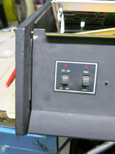
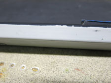
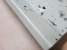
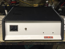
(original black) (some black removed) (side-by-side new and old) (finished panel)
Note that there is no Heathkit badge. I'm not sure if it sheared off at some point or if it was assembled without it. The screw holes contain tan plastic plugs which I removed and cleaned before repainting the panel. If I could find a replacement plastic switch legend, I would remove the old one and dip the metal to remove all paint right down to the bare metal. As it is, it looks good at a distance but you can see the underlying paint defects up-close.
To get something interesting running on this, I started with the PDP11GUI program (link), the TU58 tape emulator (link) and the XXDPv2 diagnostics (link). The PDP11GUI acts as the console and way to assemble and upload MACRO11 files to the H-11. The TU58 emulator (connected to the second SLU on the H-11) is a bootable cartridge-based mass-storage device. The TU58 archive includes a copy of the bootstrap code needed to load the tape into the H-11. Overall it works well. Next up...getting RT-11 to load.
There's only so much you can do without a floppy disk system but the TU58EM is flexible enough that you can build a bootable TU58 image that's based on an RK (1.6MB) or RL (10MB) removable cartridge disk. To get this to work, I turned to Malcolm Macleod and his work restoring a PDP-11/03 (link), with troubleshooting assistance from Mattis Lind (and to both of whom I owe a lot of thanks). Basically, the process is to use the SIMH PDP-11 emulator (link) or Ersatz-11 (link) to take an existing RT-11 v4 distribution image and change the boot device from RK to DD using the following incantation:
COPY/BOOT:DD RK0:RT11SJ.SYS RK0:
This image is then attached to the virtual TU58 drive (using switches to match your host COM port and baud rate) and you use the normal TU58 bootstrap to load it. I'm running at 9600 baud (the highest speed available on the SLU) and it passibly works.
There is one potential gotcha regarding the LTC. There have been reports that RT-11 will not boot, or will barf part of the way through, if the LTC (line time clock) is enabled. Depending on the version of the H-11, there may or may not be an LTC switch on the front panel. Instead, there is a jumper on the power supply board. What users frequently did was drill their own switch into the panel and connect it to this jumper (J3 on the schematic). This is what the prior owner of my machine did. I have not seen an issue booting with the LTC enabled, but I jumpered it anyway to disable it (this will prove to be necessary per the below...)
Update 4/9/2016
Over the last couple of weeks, I decided that while the TU58 Eumlator is a good starting point for a system with no mass storage, it's slow over 9600 baud. Maybe if I had a DLV11 it would be better but, alas, I don't.
So, I hunted down an Emulex UC07 Q-Bus SCSI adapter (manual) and a SCSI2SD drive emulator (link) -- both purchased on eBay. There is a general tutorial for doing this on the Vintage Computer Federation bulletin board (thread)...while it's specific to a PDP-11/83 restoration project, the overall process is similar.
Basically, the process goes something like this:
Make sure the LTC is disabled! This hung me up for almost a week until someone replied to the thread and suggested that I disable it on the CPU card.
Rearrange the peripheral cards in the cage. In mine, I installed them this way: CPU-UC07-RAM-RAM-SLU-SLU. It would probably be fine with the RAM before the UC07...might move it around later for testing.
Pick a drive to emulate. The UC07 has built-in profiles for the RA81, RA82, RA90, RA91, RA92 and RD54 drives. Depending on which you pick, you may need a bigger MicroSD card to accommodate the disk image that you'll create with SIMH. I picked an RD54 (150MB) drive since all I had handy was a 256MB uSD card.
Configure the SCSI2SD using the software provided with the board. This setup not only configures the controller part but also defines the drive geometry, ID and serial number strings for up to 4 emulated drives. An RD54 image produced by SIMH has 311200 blocks of 512 bytes.
Connect the SCSI2SD to the UC07. Make sure the SCSI2SD is powered on when running the ROM-resident utility FRD (Firmware-Resident Diagnostic).
Configure the NVRAM on the UC07. Chapter 5 of the UC07 manual has the code needed to load the FRD into RAM. This code uses DMA to copy code from ROM to RAM, so HALT the CPU when loading the code and set it to RUN before executing it. You can follow the instructions in the thread on VCFED, but certain parameters of the SCSI2SD should match the UC07, like "no parity" and "allow disconnect" options. The thread calls for setting the UC07 for "auto geometry" so it picks up the necessary geometry data from the SCSI2SD.
Build a disk image to write to the uSD card. The lowest version of RT-11 that will work is v5.1 (Table 2-1 in the UC07 manual has the minimum requirements). In the VCFED thread, there is a pointer to RT-11 v5.6 (an RA81 image) from trailing-edge.com from which a working image can be created. The thread instructions build an RA82 drive image (600MB), but simply substitute an RD54 (or other) and it works fine
Take the image created in Step 5 and write it to the blank uSD card using the dd utility.
Load and run the fixed disk bootstrap. Page 7-4 of the UC07 manual has the bootstrap code. Same proviso with DMA as in step 5.
If everything works, you should see the yellow light blink on the SCSI2SD and RT-11 should pop-up on the screen.
Enjoy!
Update 6/19/2020
This is another project that kind of went sideways. I put the system away for a year and came back to it. Something happened with the power supply (age, I'm sure, since the system was in a box) and it blew the 12v power leg and took the Heath serial cards with it. It took a month or so to source all of the odd parts to repair it, and I got it working again (but with a DEC SLU rather than the Heath card). After, I decided to harvest the cards and move them to a DEC BA11 (11/23) enclosure I was able to find in 2018. As you can imagine, that project took on a life of its own...see this page. I have subsequently sold the system to someone who is going to restore it as a H-11 (he had floppy drives and boards, but no system).
Copyright (c) 1998-2023 Richard A. Cini, Jr. (rcini at msn dot com) All Rights Reserved. All copyrights of any third parties referred to herein are hereby acknowledged. There is no warranty, either express or implied, relating to any of the content contained herein. The site maintainer shall in no event be liable to anyone for damages, including any loss of profits, lost savings, or other incidental or consequential damages arising out of the use or misuse of the information contained on this Web site. Batteries not included. You may use the information contained herein for NON-COMMERCIAL purposes only and AT YOUR OWN RISK.
Last updated 2026-04-15 20:06 -0400